|
Module Diagrams |

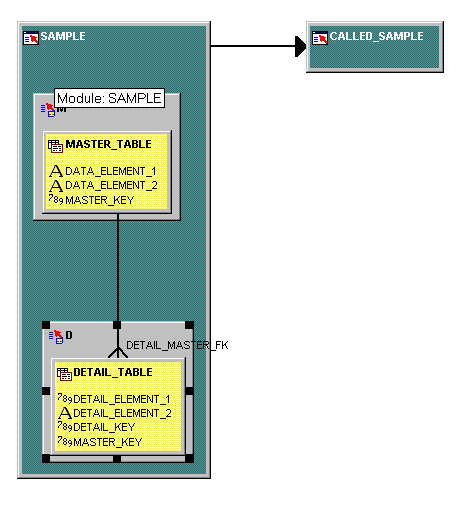
This diagram shows the database relationships between items to appear in a finished form.
Each grey area is a database table with columns shown in the yellow area.
Datatypes are illustrated by icons.
The foreign key relationships between tables are shown by the lines from one block to another.
The arrow represents a navigation link to another screen.
The "crow's foot" shows the master-detail database link.

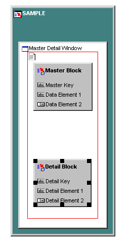
This diagram represents the two tables as items on a form.
Each grey area will be generated as a rectangle within the form window.
The items listed will become fields on the form.
Icons indicate the display type for each item.
Items will be displayed in the order shown.
Drag database items to module diagrams
Add details about display properties, help prompts, etc. (Not shown)
Run module generator